Best Practices in Implementing Security Groups for Web Application on AWS

In-Short

CaveatWisdom

Caveat: Its easy to assign source as large VPC wide CIDR range (ex: 10.0.0.0/16) in Security Groups for private instances and avoid painful debugging of data flow however we are opening our systems to a plethora of security vulnerabilities. For example, a compromised system in the network can affect all other systems in the network.

Wisdom:

  1. Create and maintain separate private subnets for each tier of the application.
  2. Only allow the required traffic for instances, you can do this easily by assigning “Previous Tier Security Group” as the source (from where the traffic is allowed) in the in-bound rule of the “Present tier’s Security Group”.
  3. Keep Web Servers as private and always front them with a managed External Elastic Load Balancer.
  4. Access the servers through Session Manager in the System Manager Server.

In-Detail

Some Basics

Security Group is an Instance level firewall where we can apply allow rules for in-bound and out-bound traffic. In-fact security groups associate with Elastic Network Interfaces (ENIs) of the EC2 instances through which data flows.

We can apply multiple security groups for a instance, all the rules from all security groups associated with instance will be aggregated and applied.

Connection Tracking

Security Groups are stateful, that means when a request is allowed in Inbound rules, corresponding response is automatically allowed and no need to apply outbound rules explicitly. This is achieved by tracking the connection state of the traffic to and from the instance.

It is to be noted that connections can be throttled if traffic increases beyond max number of connections. If all traffic is allowed for all ports (0.0.0.0/0 or ::/0) for both in-bound and out-bound traffic then that traffic is not tracked.

Scenario

Let’s take a three-tier web application where the front end or API receiving the traffic from users will be the Web tier, application logic API lies at App tier and Database in the third tier.

Directly exposing the web servers to the open internet is a big vulnerability, it is always better to keep them in a private subnet and front them with a Load Balancer in a public subnet.

It is better to maintain separate private subnets for each tier with their own auto scaling groups.

Overall, we can have one public subnet and three private subnets in each availability zone where we host the application. It is recommended to use at least two availability zones for high availability.

The architecture for our three-tier web application can be as below.

    Architecture for 3-tier Web Application
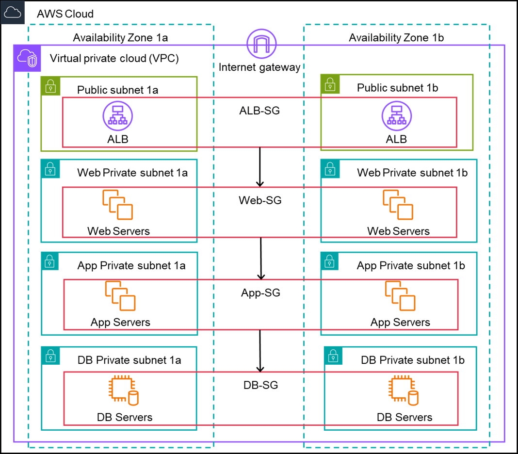
    Architecture for 3-tire Web Application

    Chaining Security Groups

    In the above architecture Security Groups are chained from one tier to the next tier. We need to create a separate security group for each tier and a security group for load balancer in the public subnet. For Application load balancer, we need to select at least 2 subnets, 1 in each availability zone.
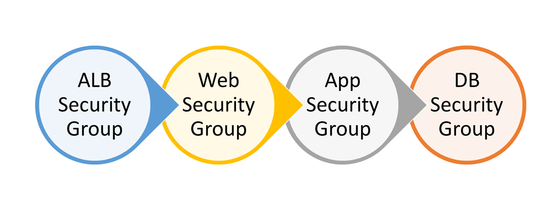
    Implementing Chaining of Security Groups

    1. A Security Group ALB-SG for an External Application Load Balancer should be created with source open to internet (0.0.0.0/0) in the Inbound rule for all the traffic on HTTPS Port 443. TLS/SSL can be terminated at the ALB which can take the heavy lifting of encryption and decryption. An ID for the ALB-SG will be created automatically let’s say sgr-0a123.
    2. For Web tier a Security Group Web-SG with the source as ALB-SG sgr-0a123 in the Inbound rule on HTTP port 80 should be created. With this rule only connections from ALB are allowed to web servers. Let the ID created for Web-SG be sgr-0b321.
    3. For App tier a Security Group APP-SG with the source as Web-SG sgr-0b321 in the Inbound rule on Custom port 8080 should be created. With this rule only connections from Instances with Web-SG security group are allowed to App servers. Let the ID created for App-SG be sgr-0c456.
    4. For Database tier a Security Group DB-SG with the source as App-SG sgr-0c456 in the Inbound rule on MySQL/Aurora port 3306 should be created. With this rule only connections from Instances with App-SG security group are allowed to Database servers. Let the ID created for DB-SG be sgr-0d654.
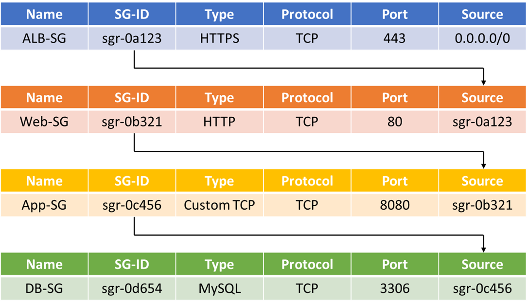
    Planning and Managing Amazon VPC IP Space in an Amazon EKS Cluster

    For the sake of simplicity, I will discuss only IPv4 addressing in this post, I will discuss IPv6 addressing in another blog post.

    In-Short

    CaveatWisdom

    Caveat: Planning Amazon VPC IP space and choosing right EC2 instance type is important for Amazon EKS Cluster, or else, Kubernetes can stop creating or scaling pods for want of IP addresses in the cluster and our applications can stop scaling.

    Wisdom:

    1. Create larger VPC with CIDR range like 10.0.0.0/16 and if needed add additional CIDR ranges to VPC with custom CNI networking
    2. Create Subnets with sufficient IPs and if needed use different subnet for secondary ENIs (network interfaces)
    3. Choose right type of instance which can support appropriate number of IPs
    4. Manage the IP allocation to Pods and creation of ENIs

    In-Detail

    Some Basics

    Amazon VPC is a virtual private network which you create to logically isolate EC2 instances and assign private IP addresses for your EC2 instances within the VPC IP address range you defined. A public subnet is a subnet with a route table that includes a route to an internet gateway, whereas a private subnet is a subnet with a route table that doesn’t include a route to an internet gateway.

    Kubernetes is an open-source container orchestration system for automating software deployment, scaling, and management. It creates Pods, each Pod can contain one container or a group of logically related containers. A Pod is like an ephemeral light weight virtual machine which will have its own private IP Address, this Pod’s IP address is assigned by kube-proxy which is a component of Kubernetes.

    Amazon EKS is a managed Kubernetes service to run Kubernetes in the AWS cloud, it automatically manages the availability and scalability of the Kubernetes control plane nodes responsible for scheduling containers, managing application availability, storing cluster data, and other key tasks.

    Kubernetes support Container Network Interface (CNI) plugins for cluster networking, a suitable CNI plugin is required to implement Kubernetes Networking Model. In Amazon EKS cluster, Amazon VPC CNI plugin is used which is an opensource implementation. This VPC CNI plugin allocates the IP address to pods on each node from the VPC CIDR range.

    In the above sample Amazon EKS Cluster Architecture, the control plane of Kubernetes is managed by Amazon EKS in its own VPC and we will not have any access to it. Only the worker nodes (Data Plane of K8s) can be in a VPC which is managed by us.

    The above VPC has a CIDR range 192.168.0.0/16 with two public subnets and two private one each in an availability zone, an Internet gateway attached to VPC, an Application Load Balancer which can distribute traffic to worker nodes and VPC endpoints which can route traffic to other AWS services.

    The NAT gateways are in the public subnets which can be used by worker nodes are in private subnets to communicate to AWS Services and Internet.

    Amazon EKS cluster is created with VPC CNI add-on which is represented at each worker node, and each worker node can have multiple Elastic Network Interfaces (ENIs)(one primary and others secondary).

    The Story

    Let’s say a global multi-national company which have thousands of applications running on on-premises Kubernetes installation have decided to move to AWS to take advantage of scalability, high-availability and also to save cost.

    For large migrations like this, we need to meticulously plan and migrate the workloads to AWS, there are many AWS migration tools which will make our job easy which I will discuss in another blog, for this post let us concentrate on planning our Amazon EKS cluster from networking perspective.

    Let us discuss three main things from networking perspective

    1. Planning VPC CIDR Range
    2. Understanding Subnets and ENIs
    3. Choosing the right EC2 Instance types for worker nodes
    4. Managing the ENIs and IP allocation to Pods

    When we add secondary VPC CIDR blocks we need to configure VPC CNI plugin in the Amazon EKS cluster so that they can be used for scheduling Pods. Amazon VPC supports RFC1918 and non-RFC 1918 CIDR blocks, so EKS Clusters in Amazon VPCs addressed with CIDR blocks in the 100.64.0.0/10 and 198.19.0.0/16 ranges with Hybrid networking models, i.e., if we would like to extend our EKS cluster workloads to on-premises data centres we can you those CIDR blocks along with CNI custom networking. We can conserve the RFC1918 IP space in a hybrid network by leveraging RFC6598 addresses.

    1. Planning VPC CIDR Range

    We should be planning a larger CIDR block for VPC with netmask of /16 which can provide up to 65536 IPs, this allows us to add new workloads for ever expanding business requirements. If we run out of IP space in this primary range then we can add secondary CIDR blocks to the VPC.  We can add up to 4 additional CIDR blocks by default and request a quota increase up to 50 including primary CIDR block. Even though we can have 50 CIDR blocks we should be aware that there is a Network Address Usage (NAU) limit which is metric applied to resources in VPC, by default NAU units per VPC will be 64000 and the quota can be increased up to 256000. So practically we can have only 4 CIDR Blocks with netmask of /16.

    2. Understanding Subnets and ENIs

    The CIDR range of public subnets can be smaller with netmasks like /27 and /24. We can plan public subnets to be smaller in size to host only NAT Gateways and bastion hosts, at the same time we need to have at least 6 free IPs which can be consumed by Amazon EKS for its internal use, this can be for creating network interfaces by Amazon EKS in the subnets.

     We don’t want to expose our application workloads to public internet so mostly we will be hosting our workloads in private subnets which should be larger in size. In the example architecture above we have use netmask /20 for private subnets which can support 4096 IPs (few of them will be reserved for internal use).

    In a worker node, the VPC CNI plugin automatically allocates Secondary ENIs (Elastic Network Interfaces) when the IP addresses from the Primary Network Interface get exhausted. Secondary Network Interfaces created by VPC CNI Plugin will be in the same subnet as Primary Network Interface by default, some times if there are not enough IP addresses in the Primary Interface Subnet, we may have to use a different Subnet for Secondary ENIs, this can be done by Custom Networking with VPC CNI plugin.

     However, we need to be aware that when we enable custom networking, IP addresses from Primary ENI will not be assigned to Pods, so multiple secondary ENIs with different subnets will be helpful but we will be wasting one ENI that is the primary ENI.

    3. Choosing the right EC2 Instance types for worker nodes

    The number of Secondary ENIs attached to the EC2 Instances (worker nodes) depends on the type of the EC2 Instances. Each EC2 instance type has a maximum number network interfaces that it can support and also there a maximum limit of Private IPv4 addresses which a network interface can handle again based on EC2 Instance type.

    We need to analyse the CPU and memory requirements of Pods hosting our application containers and number of Pods which will be scaled during minimum and maximum traffic periods. Then we need to analyse how many EC2 instances will be scaled.

    Based on these factors including the ENIs and IPs which the instance can handle we need to choose the right type of Instance.

    Pods scaling and Instance scaling in an EKS cluster is a big topic which I will be discussing in a separate blog, one thing we need to keep in mind is EC2 Instance type also affects the IP address allocation to Pods.

    4. Managing the ENIs and IP allocation to Pods

    We might go for smaller instance types and small clusters to save cost or may be various other business reasons, it becomes very important to manage the IPs in the small clusters to save cost, for this we need to understand how VPC CNI works.

    VPC CNI has two components, aws-cni and ipamd (IP address management daemon). aws-cni is responsible for setting up Pod-to-Pod communication network and ipamd is a daemon in the Kubernetes which is responsible for managing ENIs and a warm-pool of IPs.

    To scale out Pods quickly it is necessary to maintain a warm pool of IPs because provisioning a new ENI and attaching it to an EC2 instance can take some time, so ipamd attaches an ENI in advance and maintain a warm pool of IPs.

    Let us understand how ipamd allocates ENI and IPs with an example

    Let’s say we have planned for M5.4xLarge instance in the subnet which have 256 IP range. Each M5.4xLarge instance can support up to 8 ENIs and each ENI can support up to 30 IPs. Out of 30 IPs one IP will be reserved for internal use.

    When the instance is added to EKS cluster, it starts with one ENI which is primary, if the number of Pods running in the instance is between 0 to 29 then to keep a warm pool of IPs ipamd requests EC2 service to allocate one more secondary ENI, so that the total ENIs will be 2 and warm pool of IPs available in the starting will be 58 for the Instance, when the number of running Pods becomes 30 (>29) then ipamd will request for one more ENI which will increase total ENIs to 3 and IPs for the instance to 87. This can increase so on based on number of running Pods and till the EC2 instance supports ENI.

    So, the formula for number of IPs is

    the number of ENIs for the instance type × (the number of IPs per ENI – 1))

    Here in this case even though number of Pods running in a Node is only 30, the IPs allocated to that node is 87. The free IPs is 87-30 = 57 which might not be used in that instance, this also leads to situation that, one instance in the subnet get more of IPs and other instances in the same subnet will starve for IPs.

    In the instance which got more IPs, other resources like vCPU and Memory can become less which are utilized by already running Pods and other instances which have free vCPU and Memory may not have sufficient IPs to run the Pods. This can create an imbalance in distribution of Pods between instances and wastage of resources at the same time escalating the cost.

    To manage such situations, we can define CNI configuration variables WARM_ENI_TARGET, WARM_IP_TARGET and MINIMUM_IP_TARGET.

    WARM_ENI_TARGET is 1 by default, so we need touch it.

    With WARM_IP_TARGET we can define the number of free IP addresses ipamd should maintain.

    With MINIMUM_IP_TARGET we can define the total number of IPs allocated to Pods.

    It is always recommended to use MINIMUM_IP_TARGET and WARM_IP_TARGET together, which will reduce the API calls made by ipamd to EC2, which can slow down the system.

    In the above example we can define MINIMUM_IP_TARGET = 30 and WARM_IP_TARGET = 2, this will make the ipamd to maintain 2 warm-pool of IPs after 30 Pods are running. This will give space for other Instances in the subnet to consume the available IPs.

    Increasing the Pod Density per Node

    To increase Pod density per node we can enable Prefix mode with which we can increase the number of IPs allocated to Node by keeping the maximum number of ENIs same per instance. This can reduce the cost bi bin packing the Pods running per instance and use a smaller number of instances. However we need to be aware that this can affect the high availability of our applications which may need to run in multiple availability zones for high availability.